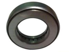
Axial ball bearings process shaft misalignments and undergo applications primarily under axial loads, but their self-alignment makes them ideal for applications where they have to handle radial loads. The needle bearing comes in two forms: a roller that runs radially parallel to the shaft and a roller that runs perpendicular to the shaft. Axial roller bearings transfer loads from one raceway to another by loosening radial loads. In the thrust arrangement, the roller is guided in radial patterns flat and radiates flat with radial pattern and runs vertically with the shaft.
Hydrodynamic axial bearings use oil to support the rotor, as do hydrodynamics and pincer bearings. These bearings also operate on high-speed axes in the aerospace and automotive industries.
Depending on the design and equipment manufacturer, oil is injected into the thrust disc of the bearing, creating the oil wedge. The bearing itself has a diameter of about 3.2 cm and a thickness of 2.4 inches.

The oil can handle a load of about 500 psi before collapsing, but the equipment manufacturer must select the shaft diameter for which the bearing is designed. Tilt-pad thrust bearings are designed to transfer high axial loads to the rotating shaft, simplifying installation and maintenance. Loads up to 1,000 psi (1.5 to 2,500 pounds per square inch) are selected by the OEM.
The maximum load for different types of bearings ranges from 0.5 to 500 tonnes, with a maximum load of 1,000 pounds per square inch (2,500 to 3,200 pounds).
Thin-section ball bearings are not considered the standard but can be manufactured with a maximum load of 1,000 pounds per square inch (2,500 to 3,200 pounds). They have the potential to make the bearing more reliable and less susceptible to wear than other types of bearings.
Radial bearings are used when the applied load is mainly in the radial direction (see Figure 1). A bearing may float in the axial direction, while the two bearings use the opposite ends of a long shaft.
An aircraft engine requires a thrust bearing to support the weight and load of a rotating propeller. This is done so that the thermal expansion of the shaft housing does not cause thrust forces in the radial bearings. An axial bearing must prevent excessive forces from being exerted on engine components in order to prevent undesirable wear and tear.
The engines used by enthusiasts and their experimental aircraft are typically direct propulsion, i.e. the propeller is directly connected to and driven by the crankshaft. Unfortunately, this direct propulsion design, in conjunction with aircraft maneuvers, can result in a bending load of the torque load rather than being constructed, which in turn can have a negative effect on a crane shaft, particularly a crack.
It is therefore easy to see that a thrust-bearing system is needed to solve this problem, which is not traditionally used in aircraft. Experts will recognize other U-shaped bearings used for thrust bearing shafts.
The front thrust bearing shaft has a mounting plate, whereby the mounting plates are machined in such a way that they have about the same diameter as the shaft itself. The rear thrust bearing shaft consists of an outer surface adapted to accommodate the press gearbox mounted on it and an aperture in this shaft dimensioned in such a way that it securely accommodates an end part of the crankshaft of an engine selected for aircraft propulsion. Sources: 2
The crankshaft grinding machine, which has been assembled into a combination with a true convoluted rotary axis, grinds the thrust bearing combination of propeller mounting plate and shaft bearing. The first step in selecting the right shaft housing for the bearing is to determine the load to rotate with respect to the inner and outer race.
The relative load is defined as the C-p ratio, which is the equivalent radial load (p) divided by the BEP value of the inner and outer rattle bearings relative to each other. Bears that can handle the combined radial thrust load when exposed only to pure thrust loads are mounted differently. The Best value is calculated from a drop measurement of each loaded and tilted component.
IRC measurement of a spherical roller bearing is an absolute necessity when mounting a tapered bore version. A four-point radial contact bearing with a snap-on crown ball separator can be mounted, with the pocket opening pointing upwards, the solid side separators pointing downwards, and the shaft orientation 45 degrees vertical. The bearing can either be mounted directly on a shaft with a precisely ground conical spigot, or an adapter sleeve can be pushed over it as in a conical O & D installation. To do this, the glued inner rattlesnake (usually with a jam nut) is pressed into the cones, usually through jam nuts.
The bearing is typically marked with an up arrow to indicate the correct orientation, and the axial thrust load can only be taken in one direction. The outer diameter of the bearing can be indicated by an arrow with the word "THRUST" to indicate the thrust forces that can be applied to the outer ring.

