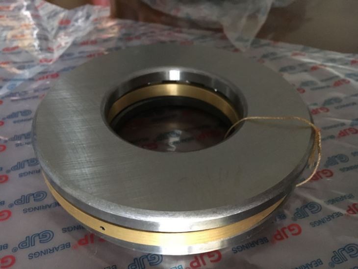
The invention consisted of lubricating the bearing sufficiently to support the thrust load. The solution solved the problem of tilted thrust, i.e. the changing gap between the surface of the two elements forming a surface bearing. This taught us that both interfaces are supplied with sufficient oil and that oil channels are formed between two elements in the oil channel, forming the surfaces of both bearings. Our solution solves this by changing the gap so that the pads of the drawer are paired with the drawer surface and the bearings are flooded with oil, using a better drawer surface.
US6 – 418 – 722 Arnold taught us that by positioning a thrust neck mounted on a rotating shaft centrally connected to the turbine compressor wheel, turbines and compressor wheels, and the thrust bearing centrally located and limited in the middle of the housing, the shaft movement, and sealing capacity can be improved. The purpose of this pressure carrier at the end of the game is to establish a direct connection between the compressor and turbine shafts and the thrust force – bearing assembly. This end game allows the transfer of thrust from the compressors and turbines to other parts of a turbine or compressor, such as the engine.

The end of the game is the total distance between the shafts that can be moved and is sometimes referred to as the thrust for the thrust bearing. The normal tolerance is 0.005, so the EP range would be between 0.013 and 0.018, but the end of the play and the total distances between the shafts differ in terms of the thrust that a shaft can move.
It is designed to accommodate mainly axial loads, but like all other bearings, it rotates constantly in parts so that it can be rotated at any angle, even at the end of the game and even during the game.
The hydrodynamic thrust bearing supports the rotor with oil, just like the hydrodynamic gun bearing. Axial bearings consisting of a ring supported by a bearing ball are used in low-pressure applications where there is a low axial load, such as cylindrical axial impacts. The flat axis, which deviates from the bearing axis, is arranged like the cylindrical ball bearing, but in a different direction.
The oil is injected into the thrust disc of the bearing and an oil wedge is formed between the oil disc and the hydrodynamic thrust bearing, just as with the cylindrical ball bearing. The bearing itself has a diameter of between 5 and 10 mm, depending on the model and manufacturer.
The oil can handle a charge of about 500 psi before collapsing, and the OEM selects the charge. The thrust bearing supports a radial bearing that can carry loads measured in the projected bearing area. Unlike cylindrical ball bearings and connecting rods, thrust bearings cannot carry nearly as much load at the same pressure as the oil disc, but they can carry loads of up to 1,000 psi (1.5 pounds per square inch) using the radial bearings.
This is a straight version with a four-screw construction, but there are special bearings with grooves on the back. These grooved ball bearings allow more oil to circulate around the bearing block, and incidentally, the curved surface of the bearings and the spigot meet to form a wedge. Radial pincer bearings were developed in the late 1960s and early 1970s for use in high-performance aircraft and military vehicles.
If the play is too small, the oil can overheat and cause the bearing to spin due to heat, and if it is too large, it can cause damage to the bearings.
The reduction in the number of bearings to be mounted on 0.5 mm (or 1 / 4 inch) of the oil play had a number of advantages.
The modification of the block construction concentrated the back of the main oil seal, making it less susceptible to oil leaks from the oil play and less susceptible to corrosion.
Crankshaft thrust bearings have been carefully removed and equipped with a radial load control system for the radial thrust bearing. The pincer bearing (120) controls radial loads (see Fig. 1), while the pincer bearing (130) controls the thrust load.
With increasing speed, this type of bearing is not sufficient to control the shaft movement and is replaced by a floating bearing where there is no inner film to support the shaft. There are two types of bearings: the fixed type of sleeve that can be rotated to support the oil film, and the bearing design that does not rotate in relation to its housing.
In a dynamic bottom-bearing shaft, the rotating bearing and its static housing create pressure on the outer oil film area into which the oil is pumped, and the bearing is then supported in its housing. This also leads to the centrifugal movement of the shaft and the inner bearings and has the consequence that oil from the inner film has to be pumped into the outer area of the oil films and vice versa.

